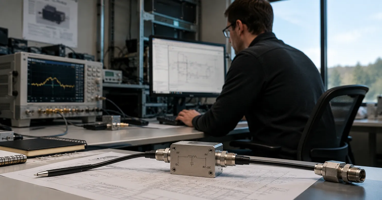
Modern RF and microwave systems are under constant pressure to do more with less — less weight, less space, less wiring complexity. One of the more practical responses to that pressure is a single-cable signal architecture: transmitting both DC power and RF signals over the same coaxial line. What sounds like a simple consolidation has far-reaching implications for how engineers design, deploy, and maintain remote RF systems.
The Case for Consolidation
In distributed antenna systems, satellite ground stations, and defense electronics, cabling is not just a logistical inconvenience — it directly affects system reliability. Every additional cable introduces a potential failure point, adds weight to aerospace or airborne platforms, and increases installation time. When a system can route both the DC bias voltage needed to power a remote amplifier and the RF signal through a single coaxial line, the architecture becomes cleaner, and the failure surface shrinks.
This is not a workaround. It is a deliberate design strategy that has been formalized across the RF/microwave industry for decades. Engineers working in radar systems, electronic warfare, and broadband test environments have long recognized that the ability to combine and then separate these two signal types — without one corrupting the other — requires precise passive components with well-defined electrical characteristics.
How Signal Separation Works in Practice
The mechanism enabling this coexistence is based on frequency-domain separation. DC current and low-frequency control signals occupy a portion of the spectrum that can be cleanly decoupled from high-frequency RF signals using passive reactive networks. An inductor blocks RF while passing DC; a capacitor blocks DC while passing RF. Together, these form a three-port network that sits in the transmission line and handles both functions simultaneously.
This is exactly where bias tees enter a system design. They serve as the interface between the DC supply path and the RF signal path, allowing both to share the same coaxial cable to a remote device — such as a low-noise amplifier (LNA) — and then be cleanly separated at the other end. The quality of that separation, measured in terms of insertion loss and port-to-port isolation, directly determines how much the DC path degrades the RF signal and vice versa.
What Engineers Actually Evaluate
When selecting a passive component for this function, engineers are not browsing brands. They are evaluating a matrix of parameters that must simultaneously satisfy system-level constraints. Frequency range is the most obvious: a component covering 0.5 GHz to 40 GHz will serve a fundamentally different application stack than one optimized for a narrow sub-band.
Current handling capacity matters significantly in systems where the remote device draws meaningful power — LNAs in active phased arrays, for example, or amplifier chains in satellite payloads. Voltage rating sets the upper limit of the DC supply, while isolation defines how cleanly the RF and DC paths are separated under operating conditions. VSWR indicates how well the component matches the transmission line's impedance, directly affecting reflected power and signal integrity.
Size and packaging are non-trivial in constrained environments. A component that performs well electrically but cannot fit within a rack-mount chassis, or a compact airborne enclosure, provides limited practical value.
Where Single-Cable Architecture Shows Up
Remote powering of LNAs in antenna feeds is the most common application. Rather than running a separate DC cable from the supply to the amplifier mounted at the antenna, the DC bias rides the same coaxial line as the RF signal. At the antenna end, the DC is extracted to power the LNA; at the base station or receiver end, it is isolated from the signal chain.
This same approach appears in cable television distribution, satellite link equipment, and increasingly in 5G base station infrastructure, where remote radio units (RRUs) are mounted far from baseband equipment. The principle remains consistent regardless of frequency band or application domain.
Design Verification Considerations
For engineers moving from concept to prototype, characterizing a single-cable architecture requires network analyzer measurements across the full operating band. S-parameter data — particularly S21 for insertion loss and the DC port isolation — tells the story of whether the passive network is performing within margin. Phase response across the RF band is also worth evaluating in phase-sensitive systems such as beamforming arrays.
Thermal behavior under sustained DC current load is another verification step that is often deferred until late in the design cycle, only to become an integration problem. Rating a component for 1.5A continuous operation does not mean all deployment environments will handle the resulting thermal dissipation gracefully.
The Broader Engineering Principle
Single-cable architectures represent a broader principle that applies well beyond RF electronics: the value of shared infrastructure scales with deployment complexity. A decision that may seem like a minor component of choice at the bench often determines installation costs, serviceability, and system longevity in the field.
For any engineer evaluating whether to consolidate their DC and RF paths, the question is less about whether it can be done — it reliably can — and more about which performance constraints define the outer limits of what the application will tolerate.