Among the most consequential but least visible components in UAE industrial pipeline systems are surge vessels. They sit quietly at pump stations and pipeline junctions, apparently doing nothing — until the moment a pump trips, a valve closes too fast, or an emergency shutdown activates. In that moment, they absorb the pressure wave that would otherwise travel destructively through the pipeline system, protecting pumps, valves, pipe joints, and instrumentation from hydraulic shock loads they were not designed to withstand.
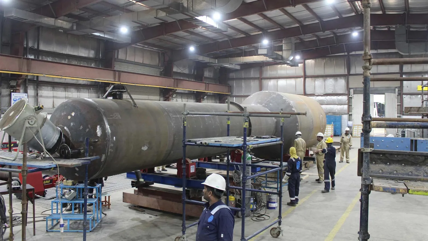
The difference between a pipeline system with adequate surge protection and one without becomes apparent the first time a major transient event occurs. With protection: the instrumentation records the transient, the surge vessel absorbs it, and operations continues. Without protection: pipes burst, pump casings crack, valve bodies fail, and the facility shuts down for emergency repairs at a cost that dwarfs the surge protection investment many times over.
BERG Industries is among the most experienced surge vessels manufacturing companies in UAE, combining hydraulic engineering capability for surge analysis with ASME pressure vessel fabrication expertise for code-compliant vessel manufacture. We design surge vessels that actually work — sized from hydraulic transient analysis of the specific pipeline system — and build them to the quality standard that UAE oil and gas, water, and industrial clients require.
Hydraulic Transient Analysis: The Engineering Foundation of Surge Vessel Sizing
A surge vessel that is sized without hydraulic transient analysis may provide some protection — but there is no engineering basis for confidence that it will limit peak pressures to acceptable levels during the worst-case transient events the pipeline will actually experience.
Hydraulic transient analysis is a computational simulation of the specific pipeline system. It models the pipeline geometry, the fluid properties, the pump characteristics, the valve closure rates, and the initial steady-state conditions to calculate the pressure wave that propagates through the system during worst-case operational events. The analysis output — maximum transient pressure, maximum transient volume that must be accommodated, and the gas cushion pressure range within which the surge vessel must operate — is the specification from which the vessel is designed.
BERG Industries' engineering team performs or reviews hydraulic transient analysis as part of our surge vessel projects, ensuring that the vessel design is based on the actual hydraulic requirements of the pipeline system rather than on rules of thumb that may produce vessels that are significantly undersized or oversized for the application.
Pressure Vessels: The Broader Static Equipment Family
Pressure Vessels manufacturer in UAE capability at BERG Industries covers the complete pressure vessel scope alongside surge vessel manufacturing — separators, slug catchers, flash drums, filter vessels, accumulators, and storage bullets, all designed to ASME Section VIII Division 1 or equivalent codes.
For UAE projects with both surge vessels and other pressure vessel requirements, single-source supply from BERG Industries provides consistent documentation, coordinated inspection scheduling, and a single quality management system covering the complete equipment scope.
Static Equipment: Complete Process Containment Supply
Static Equipment Manufacturer capability at BERG Industries extends to the broader static equipment family — heat exchangers, columns, reactors, filter vessels, and storage tanks. For project teams with multiple static equipment requirements, BERG Industries' single-source capability simplifies procurement and provides consistent quality across all items.
Piping Fabrication: Connecting Surge Protection to the System
Piping fabrication for surge vessel installations must be rated to the pipeline's full operating pressure class and fabricated with qualified welding procedures. When piping and vessel fabrication are both within BERG Industries' scope, dimensional coordination happens in our factory — vessel nozzle positions confirmed and connecting pipe spools fabricated to match — preventing the installation conflicts that arise when separately procured scopes have different dimensional interpretations.
Heat Exchangers: Process Equipment Requiring Surge Protection
Many heat exchanger systems — particularly pump-fed cooling circuits and feed/effluent exchangers — are vulnerable to pressure transients when associated pumps trip. Heat Exchangers Manufacturer in UAE capability at BERG Industries allows us to supply both the heat exchangers and the surge protection for connected pipeline systems under a single scope — with the surge vessel sizing coordinated with the heat exchanger's nozzle loading limits to ensure that transient loads on exchanger connections remain within acceptable bounds.
Conclusion: Surge Protection Requires Engineering Depth
A surge vessel from a manufacturer who performs hydraulic transient analysis and designs the vessel to the analysis results provides genuine pipeline protection. A surge vessel from a manufacturer who sizes from rules of thumb provides uncertain protection. For UAE pipeline operators whose assets are worth hundreds of millions of dirhams, the engineering investment in correct surge protection design is the clearest example of risk mitigation that pays for itself many times over in avoided incident costs.
BERG Industries' combined hydraulic engineering and pressure vessel fabrication capability provides UAE pipeline operators with surge protection that is designed correctly, built to quality standards, and documented completely.
Frequently Asked Questions
Q1. At what points in a pipeline system should surge vessels be installed?
Surge vessel installation points are determined by the hydraulic transient analysis — the locations where the analysis shows unacceptable peak transient pressures without protection. The most common installation points are at pumping stations — immediately downstream of the pump discharge check valves — where pump trip transients originate. For long pipelines with multiple pump stations, each station typically requires its own surge protection. In distribution networks where multiple consumer connections create demand variation transients, surge vessels may be required at distribution nodes as well as at the main pumping station. The hydraulic analysis identifies which locations require protection and what vessel size is needed at each location — it is not possible to determine the optimal installation locations without performing the analysis.
Q2. How does BERG Industries coordinate the surge vessel design with the hydraulic engineer when the transient analysis is performed by a third party?
When the hydraulic transient analysis is performed by the client's own engineering team or by a specialist consultant, BERG Industries receives the analysis results — maximum transient pressure, maximum transient volume, and required gas cushion pressure range — as the design basis for the surge vessel. We review these inputs against the analysis methodology to ensure they are consistent with the vessel sizing calculation approach, flag any inconsistencies or apparent conservatisms that could be optimized, and confirm the design basis before proceeding to vessel design. For vessel designs that differ significantly from what the analysis results suggest — larger or smaller than the analysis implies — we raise this with the hydraulic engineer for confirmation before finalizing the design.
Q3. What is the pre-charge pressure for a surge vessel, and how is it set during commissioning?
The pre-charge pressure is the nitrogen gas pressure in the vessel before any process fluid enters during operation. It is determined during the hydraulic design as the maximum system static pressure minus the minimum transient pressure drop — set to ensure that the gas cushion expands into the connecting piping during the low-pressure phase of the transient cycle, preventing vacuum conditions that can cause pipe collapse in thin-walled systems. During commissioning, the vessel is charged to the pre-charge pressure using a nitrogen bottle and pressure regulator before the system is filled with process fluid. The pre-charge pressure is set with the vessel isolated from the pipeline, verified by pressure gauge, and recorded in the commissioning record. It should be checked during each planned maintenance interval and recharged if it has dropped below the acceptable range.
Q4. How is a surge vessel documented and what certificate is required for UAE oil and gas service?
A surge vessel for UAE oil and gas service requires documentation consistent with the applicable pressure vessel code. For ASME Section VIII vessels, the documentation package includes the manufacturer's data report (Form U-1), design calculations, material test certificates, weld records, NDE reports, and hydrostatic test certificate. Third-party inspection — by an ASME-authorized inspection agency such as Lloyd's Register, Bureau Veritas, or SGS — witnesses defined hold points during manufacture and signs the manufacturer's data report, certifying code compliance. The U-1 data report is stamped with the ASME U-stamp, indicating that the vessel was manufactured by an ASME-authorized manufacturer under the witnessing of an authorized inspection agency. For vessels requiring registration with the UAE regulatory authorities — vessels above defined size or pressure thresholds — the documentation package includes the registration application materials as specified by the applicable regulatory requirement.
Q5. Can a surge vessel be designed for installation in an ATEX Zone 2 classified area?
Yes. Surge vessels for installation in ATEX Zone 2 classified areas are designed with the same pressure vessel engineering as standard surge vessels, with additional considerations for the hazardous area installation. The vessel material and sealing system must be compatible with the specific hazardous atmosphere — confirmed through the material compatibility assessment for the classified area's gas group and temperature class. Any pressure gauges, level indicators, or instrumentation installed on the vessel in the classified area must be selected with ATEX certification appropriate for Zone 2 and the gas group. Electrical bonding and earthing of the vessel to the site earthing grid must be confirmed to prevent static charge accumulation — important for vessels handling flammable fluid in classified areas where static discharge could create an ignition source. The installation documentation for civil defense and operating company approval should include the ATEX compliance assessment for all Zone 2 installations.